


"Live" Evaluation with Integrated Software in Thermal Cameras
In this chapter, we provide some clarifications regarding the calibration of thermal cameras, then detail the advantages of on-site evaluation functions of mobile thermal cameras.
There is often a demand for thermal cameras to be able to measure "higher" temperatures. As if this were a difficult task! But it's not. Most (even the cheapest) thermal cameras measure up to a minimum of 120 °C, but there are plenty of low-cost and standard thermal cameras with extended measurement ranges up to 200, 250, or 350 °C. A more interesting question is at what Celsius temperature their measurement capability starts, at what resolution (with how many bits of digitization), and how many selectable measurement ranges they cover to fully represent their measurement capability. Because only with all the listed data it becomes clear what capability and measurement accuracy (quality) the given thermal camera has. We addressed the digitalization of temperature values and the lower limit of the thermal camera's measurement range in the previous chapter; now we continue with the upper limit of the measurement range.
Simplicity with the Upper Value
The upper limit of the measurement range (highest range) of thermal cameras is much simpler from a measurement technology perspective because, due to the mentioned radiation physics laws, there is abundant detectable radiation from high-temperature objects. At most, by appropriately shortened integration times, and (in higher ranges) by using appropriate filters, we need to ensure that the sensor remains in the linear detection range (and of course, not "burning out"). For low-cost thermal cameras, instead of internal filters, appropriate filters with sufficient attenuation (sufficiently low transmittance) that can be screwed in front of the lens are used to extend the measurement range. This is a particularly inexpensive solution, but certainly not very useful in terms of measurement accuracy.
However, there is another practical technical limit to calibrating really high temperatures. Currently, the warmest hollow reference radiators approach a maximum of 2000 °C or 2500 °C, which are 99.9999% close to the ideal radiator (black body). Calibrating to even higher temperatures can only be achieved with mathematical tools (extrapolation), which unfortunately have serious uncertainties.
A Clear Picture of Calibration
In the following, we also provide some additional information on the calibration of thermal cameras and calibration ranges because certain terms are often misleadingly used.
1) The measurement (or calibration) ranges of thermal cameras always refer to the radiation of a black body: thus, due to the lower emissivity capability of practical objects, higher temperatures can be measured at the measurement limit, precisely and without endangering the thermal camera. For example, a radiator with 50% emissivity emits as much long-wave radiation at 150 °C as an ideal radiator at 100 °C. And a radiator with 25% emissivity emits the same radiation only at 250 °C. (Note: these are approximate data.)
2) The post-installation and periodic recalibration (with correction) of thermal cameras with new lenses can only be performed by the thermal camera's (own) manufacturer. This is because during calibration, the thermal camera manufacturer creates a calibration data file interpreted pixel by pixel, which is stored in the thermal camera and used during pixel-by-pixel temperature calculation for correcting the properties of the sensor and the lens. However, no thermal camera manufacturer discloses this know-how to a third party.
3) If only the documentation of the measurement capability is required, then other calibration laboratories besides the manufacturers could perform this if equipped with appropriate reference radiators (one order of magnitude more accurate than the thermal camera's measurement accuracy). However, in this case, the calibration laboratory would have an incredibly huge task because they would need to document the measurement accuracy of each individual pixel at sufficiently frequent temperature values in every measurement range of the thermal camera. Compared to the automated calibration process implemented by manufacturers (which includes this), this would be an incredibly long and extensive process that would be economically unfeasible. Therefore, limiting the calibration to one or two "reference temperatures," or determining the temperature measurement accuracy only from the central pixel of the thermal image, can be considered at most a single-point temperature measurement check, but by no means the calibration of the thermal camera.
4) The certification of thermal cameras is not a real thing at all. Firstly, thermal cameras are not listed in the annex of the law listing devices to be certified, and secondly, there is no accredited institution in Hungary for calibrating thermal cameras. Therefore, in the absence of accredited calibration, no one is capable of certification. (Even if the law were to stipulate this.) Offering work with a certified thermal camera or falsely documenting such a feature could be interpreted as misleading consumers, which is punishable by the Civil Code.
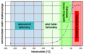 |
| Figure 1: Relationship between the measurement range and the sensor characteristic curve [source: Infratec] |
On-Site Evaluation Functions of Mobile Thermal Cameras
Thermography, as an "imaging" non-contact temperature measurement method, involves first collecting measurement data (the digitized radiation intensity value from each pixel). These values need to be processed, mathematically corrected (converted to temperature), and then displayed either immediately during the measurement (in the thermal camera) or during later evaluation. Depending on the specific measurement task, the requirements for evaluating thermal images can vary significantly. While in some cases determining the specific temperature of each pixel (measurement point) is sufficient, in other cases, correcting the emissivity value of each pixel or even capturing and evaluating complete image sequences is necessary for the desired temperature relationships or processes (e.g., in the form of temperature-time diagrams).
Often, data evaluation and display as processed temperature values are required during the measurement (even in real-time). The so-called live evaluation is practically part of the operator software in thermal cameras or its integrated extension, thus integrating its operation into the process of operating the thermal camera. Our first table lists the "automatic" auxiliary functions and real-time evaluation possibilities integrated or integrable into modern (professional) thermal cameras, without claiming completeness.
| Function | Explanation |
| Autofocus | focusing the thermal image based on the steepest temperature gradient |
The more of these functions we find in our thermal camera, the more versatile its applicability, and the more convenient and efficient on-site work becomes. From the mentioned evaluation possibilities, we would highlight the temperature-dependent start of measurement storage, which often greatly assists in recording unforeseeable thermal events. In the case of fast processes, the image sequence recording function provides the solution, utilizing the unbeatable advantage of thermography: the ability to record thermal processes that occur in fractions of seconds. Thanks to the built-in composite (sometimes referred to as fusion in some companies) image display in the thermal camera, there is no longer a need to take separate photos for documentation, which represents a significant time-saving opportunity. Moreover, through the projection of the thus realized thermal image and photograph onto each other, the graphical documentation of the object's temperature relationships can hardly be better (and more easily recognizable).
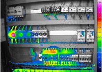 |
| Figure 2: Composite display [source: Infratec] |
Special thermographic filters for thermal cameras
There are many measurement tasks where it is not enough to select a thermal camera with the appropriate spectral sensitivity (wavelength range), but specific infrared wavelength range filters are also required to detect the object temperature or physical phenomenon to be measured. Depending on the type and design of the thermal camera, the filters need to be placed externally (in front of the lens) (such as CO2 laser protection filters) or integrated into a filter wheel inside the thermal camera, which enables software-based selection of filters (very important, for example, when examining internal components of incandescent and arc plasma light sources and glass or ceramic burners through glass surface and through-glass filters). Our 2nd and 3rd tables contain only a few of the most commonly used filters.
|
Type |
Wavelength |
Function |
|
BP |
3.6–4 µm |
reduces atmospheric effects |
|
HP |
3.6 µm |
reduces solar reflection |
|
NBP |
2.3 µm |
measurement through glass |
|
NBP |
5.0 µm |
measurement on glass surfaces |
|
BP |
3.7–4 µm |
measurement through flames |
|
BO |
3.9 µm |
expands measurement range |
|
NBP |
4.25 µm |
detection of flame temperature |
|
NBP |
4.25 µm |
polyethylene spectral line |
|
Type |
Wavelength |
Function |
|
NBP |
8.3 µm |
teflon spectral line |
|
HP |
7.5 µm |
excludes shorter wavelengths |
|
NBP |
10.6 µm |
CO2 laser protection filter |
Rahne Eric (PIM Ltd.) pim-kft.hu, gepszakerto.hu
The content of the publication is protected by copyright. Any (even partial) use, electronic or printed republication is only permitted with the indication of the source and the author's name, and with the author's prior written permission. Infringement of copyright (Copyright) will have legal consequences.
Copyright © PIM Professzionális Ipari Méréstechnika Kft.
2026 | Minden jog fenntartva
Impresszum | Adatkezelés