


Rahne Eric, B.Sc. in Electrical Engineering, founder of PIM Professional Industrial Measurement Technology Ltd., vibration diagnostics expert
The causes of machine vibrations can be diverse: alternating forces that inevitably occur during machine operation, originating from the machine's normal alternating operation or the residual unbalance of rotating components. Machine components form spring-mass oscillatory systems. Rotating machines consist of numerous such systems that are interconnected and excite each other. Vibrations are generated based on the stiffness and mass of mechanical elements: the smaller the machine element, the higher frequency but lower amplitude vibration it performs. These vibrations not only add up but also decrease as they move away from the source. (The higher the vibration frequency, the stronger the damping.) Consequently, it is advisable to measure on bearing housings in the case of rotating machines, as vibrations originating from faults in rotating components are transmitted here, and vibrations resulting from bearing faults (high frequency) can only be measured here.
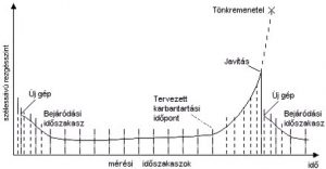
The intensity of vibration changes over the lifespan of the machine or machine component(s) due to variations in clearances, surfaces, and elasticity factors - i.e., machine wear and aging. This vibration change (trend) can be utilized as a characteristic of the rate of deterioration of rotating machine condition. Typically, vibrations are slightly higher during the run-in of new machines, followed by a long period of nearly constant low vibration levels. As the machine wears out more, vibrations gradually increase more prominently. By observing this, we can estimate the remaining service life in advance, organize component procurement and maintenance in a timely manner.
For effective evaluation of trends, it is necessary to:
Vibration intensity characterizes the mechanical condition of a given machine or machine element(s) with a single value. This value can be the peak, average, or effective (RMS) value of vibration displacement, velocity, or acceleration in a specific frequency range, commonly measured in the 10 ... 1000 Hz range (according to ISO 10816-3). Since this range is sufficient only for machines rotating faster than 600 rpm, measurements are often taken from 2 Hz. As the frequency range according to ISO 10816-3 extends only up to 1000 Hz, measurements according to this standard do not provide information on bearing condition. Bearing vibrations are of much higher frequency and poorly detectable in vibration velocity. Therefore, in addition to ISO standards, further vibration acceleration measurements at higher frequencies (typically in the 2 ... 10 kHz range) are necessary for assessing bearing condition.
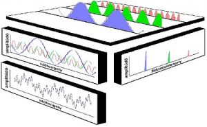
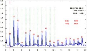
Each machine component generates and follows vibrations of various (well-identifiable) frequencies as a result of its operation. By transforming the recorded vibration-time signal into a spectrum, it becomes "visible" which frequencies of vibrations are present. Certain frequencies can be assigned to specific components and typical machine faults - of course, considering the current machine speed. The amplitude of the generated vibration is characteristic of the severity of individual machine faults.
Typical vibration frequencies of common machine faults:
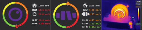
The most common "conventional" way of machine diagnostics involves preparing a database and then a measurement route on a computer in advance. Subsequently, the vibrations of the rotating machine are measured by loading this into the instrument. After transferring the data from the instrument to the computer, the measured machine vibrations are analyzed with PC software. An incredibly practical innovation is that the Synergys VShooter vibration analyzer/data collector "thinks" quite differently: First, take a photo of the rotating machine to be inspected, then mark the planned measurement locations, perform the vibration measurements. Then view the "machine condition photo," the ISO 10816-3 vibration level and bearing condition graphs, spectra, and time signals. All this immediately on the instrument's high-resolution color screen!
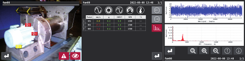
When measuring a rotating machine that has been measured before, there is no need to take a photo before the measurement: you just need to select the current machine from the instrument's memory and you can start the measurements. In addition to the displayed results listed above, you also get a trend chart, as the machine's history is known, allowing the speed of the machine's deterioration to be graphically represented immediately. (This helps estimate the remaining service life, plan spare parts procurement and maintenance in a timely manner.)

In addition to the above, you can also use the automatic vibration analysis functions of the VShooter mentioned here to thoroughly investigate any potential faults in the rotating machine. The instrument can detect imbalance, misalignment, mechanical looseness, and poor lubrication or failure of bearings. With the VShooter's built-in thermal camera, even the bearing temperature can be measured, and there is also a way to check the machine's electrical connections! Therefore, all necessary functions are available in a single, ergonomic instrument!
The instrument's memory is large enough to perform measurements on a large number of machines for years and store them in the instrument. Of course, there is also a way to save the data to a PC and print reports. PIM Professional Industrial Measurement Ltd. H-2040 Budaörs, Szabadság út 143 -1/3. Tel .: (23) 792-163 e-mail: pim@pim-kft.hu web: www.pim-kft.hu www.termokamera.hu www.gepszakerto.hu
The content of this publication is protected by copyright, and its (even partial) use, electronic or printed re-publication is only permitted with the indication of the source and author's name, and with the author's prior written permission. Infringement of copyright (Copyright) has legal consequences.
Copyright © PIM Professzionális Ipari Méréstechnika Kft.
2026 | Minden jog fenntartva
Impresszum | Adatkezelés