


Eric Rahne, B.Sc. in Electrical Engineering, Level 3 Accredited Thermography Expert (PIM Ltd.)
In our previous article, we discussed why it is important to consider the geometric resolution of our thermal camera, the pixel resolution of the thermal image, and the thermal resolution of the thermal camera. Now, let's review what makes our survey successful. Based on a thermal image captured under appropriate measurement conditions, it is relatively easy to identify thermal bridges. Where the highest temperature is observed in an outdoor image - usually well defined - a thermal bridge (or crack) is present. This requires that there is no local internal heat source (such as a heater) at that location, no reflection, or surface material differences (with different emissivity capabilities). (This needs to be verified on-site, or if omitted, based on a photograph.) In indoor images, the coldest spots usually indicate thermal bridges. We can be sure of identifying the thermal bridge when we find the "cold" surface in the interior corresponding to the external temperature rise.
It is just as easy to determine (with the same external or internal coating) which building element has better or worse thermal insulation properties. However, there are additional possibilities, so let's see what else can be examined:
To ensure effectiveness, the declared measurement conditions for building thermography need to be further narrowed down for insulation-related measurements. Because accurate (containing evaluable information) results are only obtained if the following limitations are taken seriously:
Summer assessment of residential building insulation, even with the best building climate control, is not feasible. On the one hand, it is inconceivable to maintain indoor temperatures at least 10 K lower than the ambient temperature for a minimum of 5 days (Consider night cooling too!). On the other hand, the thermal equilibriums suitable for the actual heating season do not occur (e.g., different flow conditions due to varying heating/cooling locations). However, the summer season is recommended for inspecting refrigeration rooms, freezer tunnels. (These should not be heated in winter for thermographic inspection.) During winter inspections, to capture better images, heating should not be increased immediately before the inspection. The result will be the opposite, as it will create strong heat effects, but only disturbing transient temperature distributions. Their evaluation is usually not only more difficult compared to measurements made at a constant lower temperature, but often simply impossible. For outdoor insulation inspections, it is very important that the external wall layer heating caused by daytime sunlight does not affect our measurements. It is advisable to start the measurements at least 2–3 hours after sunset in the order of north, east, south, west-facing wall surfaces. This way, it is ensured that the wall surface exposed to sunlight last can cool down for the longest time. Of course, this order is not so important for an early morning measurement due to the overnight cooling. Routinely following this order can facilitate the conduct and documentation of surveys.
A strictly closed external opening does not mean that the occupants cannot use the entrance doors or ventilate their apartment (even on the day of the inspection). These ventilation periods (assuming proper ventilation) are too short for the warm air escaping or cold air entering during this time to distort the temperature distribution of the bridging elements or openings. However, prolonged or even "continuous" ventilation with tilt-and-turn windows (which is energetically unfavorable anyway) is prohibited. For example, warm air flowing out for a long time can result in a heat distribution above the window that may raise suspicions of a thermal bridge in an inexperienced thermographer. Since most measurement objects in building thermography have high emissivity capabilities and their temperatures only moderately differ from the ambient temperature, setting the emissivity factor to 92 percent typically causes measurement errors of less than +/- 0.1°C.
Moreover, setting the emission factor to 100 percent only leads to an error of a few tenths of a degree, while exempting us from providing the environmental temperature. Let us now look at examples of the causes of thermal bridges.
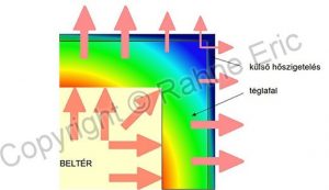
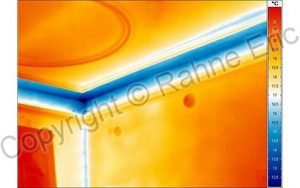
A common problem in buildings with angular designs is the so-called geometrical thermal bridge, which can occur in both uninsulated and insulated buildings. A typical example is the temperature distribution that occurs at external (or so-called positive) corners, where the warm-side "entry" surface has a smaller area than the cold-side exit surface. Consequently, the external surface at the corner releases heat from a smaller area fed by a smaller heat flow than the straight section of the wall. As a result, the internal surface cools down at the corner. This thermal bridge resulting from the geometrical design does not pose a problem in practice until the temperature of the inner surface drops below the dew point temperature.
To meet building structural requirements, concrete beams, steel beams, concrete pillars, concrete rings, and other reinforced concrete structural elements are often used. It is well known that their thermal conductivity can be much higher than the building material (e.g., hollow brick) used in the wall. To mitigate the resulting thermal issues, these elements are usually equipped with local insulation. However, a common problem is that this is often done in a thoughtless cost-saving manner. It seems that many builders believe that heat always spreads horizontally (or vertically). In reality, heat transfer occurs in all directions, through materials with the lowest thermal resistance (best thermal conductivity). This thermal bridge, resulting from inadequate insulation, occurs both in externally insulated and uninsulated external walls (although less severely in the latter case). To prevent it, the additional insulation layer should be only a few centimeters wider. The following figures vividly illustrate the effect of insufficient insulation on externally insulated walls. For the sake of simplicity, only the problematic heat flow is indicated.
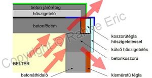
The next figure illustrates the "economical" implementation of post-insulation. The existing wooden covering under the eaves was not removed during insulation installation, so no insulation was placed behind it on the wall surface. As a result, the wooden covering directly contacts the internal air space at a temperature corresponding to the external air temperature, due to the completely uninsulated concrete ring and concrete ceiling. A more pronounced thermal bridge cannot be imagined. Due to concealment, the thermal effect of this thermal bridge is completely imperceptible from the outside. However, from the inside, the upper edge of the wall is almost dripping with moisture due to dew point temperatures under the mold layer. Let this be a warning example that building thermography strictly requires both external and internal surveys.
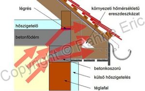
Note: The effects of the insulation error shown in the above figure are not visible from the outside, as the wooden covering is naturally ventilated, so its temperature matches that of the outdoor air.
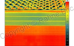
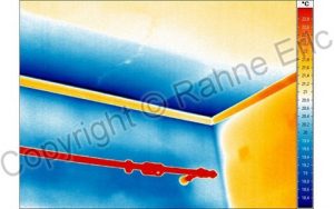
The thermal image on the left proves that the thermal effects of the insulation error detailed in the previous figure are not visible from the outside: the lower part of the wooden covering has a temperature matching the air rising on the wall, while its vertical plane has a temperature matching that of the outdoor air.
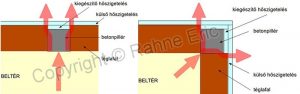
The aforementioned phenomena can partly arise due to design errors. Let us consider just one "special" example from the multitude of errors that have arisen clearly due to the cost-saving efforts or professional ignorance of the contractor: the thermal bridge resulting from the ill-considered simplification of terrace insulation shown in the figure below. Here, on the one hand, the metal sheet introduces the external temperature into the concrete slab, and on the other hand, the upper concrete layer, which does not reach the insulation of the ring brick, also forms a thermal bridge between the ring brick and the exterior.
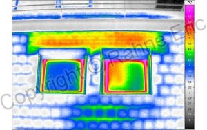
It is also evident here that external error detection would not have been sufficient, as the ineffective external insulation material edge conceals the real problem: the thermal bridge caused by the metal sheet closure of the terrace and the undersized insulation layer beneath the upper concrete layer. From an internal thermal image perspective, it is interesting to note that the extent of the built-in metal sheet can be almost entirely recognized. Furthermore, an imperceptible crack is visible on the ceiling. Eric Rahne (PIM Ltd.) pim-kft.hu, termokamera.hu
The content of the publication is protected by copyright, its (even partial) use, electronic or printed re-publication is only permitted with the indication of the source and the author's name, and with the prior written permission of the author. Infringement of copyright (Copyright) has legal consequences.
Copyright © PIM Professzionális Ipari Méréstechnika Kft.
2026 | Minden jog fenntartva
Impresszum | Adatkezelés