


Eric Rahne, B.Sc. in Electrical Engineering, Level 3 Accredited Thermography Expert (PIM Ltd.)
In addition to our previous article on thermal imaging of electrical equipment, with this publication, we aim to provide further practical advice for professionals performing such measurements to determine the real temperature of equipment as efficiently and with as little measurement error as possible. Considering that undersized or damaged conductors, poor connections (due to increased transitional resistance), and in most cases electrically faulty devices heat up to temperatures higher than usual (permissible), the necessity of maintenance can be primarily assessed by identifying the heating spots. However, since heating typically occurs only during operation (under voltage), a measurement method that allows for contactless temperature sensing is advantageous. There are fundamentally two categories of devices available for this purpose: infrared thermometers (often incorrectly referred to as "point thermometers" or even more erroneously as "laser thermometers"), or thermal cameras suitable for graphical representation of surface temperature distribution, also known as thermographic cameras, or infrared cameras. The main advantage of both devices is that measurements can be safely performed from a distance - even on equipment operating at several kV - without affecting the operation of the equipment being examined. However, it is crucial to know and take into account during measurement evaluation that both types of measuring instruments determine the surface temperature of the object based on the detection of infrared radiation (thermal radiation), which has very serious physical (theoretical) limitations. The practical implications of these limitations are as follows.
Also, during the execution of practical measurements, it is important to consider that both infrared thermometers and thermal cameras are optical instruments capable of detecting heat radiation from only a specific geometric resolution of the measured object's surface. In practice, this means that for small objects or measurements from long distances (e.g., on overhead lines), the geometric resolution provided by the contactless temperature measuring device (whether a thermal camera or an infrared thermometer) must be taken into account. For very small objects or measurements from very long distances, averaging the background and object temperatures (assuming a higher temperature object) may result in incorrect, lower object temperatures being displayed. The greater the temperature difference between the object and the background, the larger the measurement error will be! Additional important considerations and rules In the case of infrared thermometers, the 20:1, 30:1, or 50:1, or 60:1 value characteristic of their optics determines how suitable they are for measuring the temperature of electrical equipment, as well as the smallest measurable object and the maximum measurement distance. With a 20:1 optics infrared thermometer, the average temperature of a 1 m diameter circular surface is displayed from a distance of 20 m. From a distance of 1 m, this surface is approximately 50 mm in diameter. (In practice, an infrared thermometer with such optics is hardly suitable for measuring the temperature of electrical equipment, as - due to safety regulations - measurements on high-voltage equipment must be taken from greater distances, and for low- and medium-voltage equipment, the object sizes are smaller than 50 mm.) Therefore, it is advisable to use infrared thermometers with 50:1 or 60:1 optics for the condition monitoring of electrical equipment. With a 60:1 instrument, the temperature of an object as small as 16 mm can still be detected from a distance of 1 m, assuming that the measuring surface (ideally marked with at least 2 laser points in better instruments) does not protrude from the surface of the object being measured (cable, connector, contact).


When using thermal cameras, it is important to follow the rule that at least three elemental pixels should fall onto each measurement surface to ensure the correct evaluation of the measured temperature data. If this rule is not followed, there is a high probability that only pixels showing the average temperature of the object surface and background will appear in our thermal image. To determine the smallest object that can be measured with a particular thermal camera and the maximum allowable measurement distance (these two values are of course interdependent), the IFOV parameter (instantaneous field of view, smallest elemental viewing angle) included in the technical data of the thermal camera must be known. This parameter specifies the viewing angle that characterizes the mapping of a unique sensor (pixel). For example, the value of 1.5 mrad indicates that each measurement point projected onto the object at a distance of 1 m has a diameter of 1.5 mm, and at a distance of 2 m, the projected area has a diameter of 3 mm, and so on. (This should be imagined as the beam of a flashlight, which covers an increasingly larger circular area depending on the distance.) If necessary, the geometrical resolution must be adjusted to the size/distance of the object by using appropriate optics (special telephoto lens).


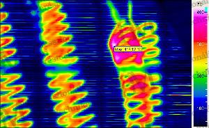
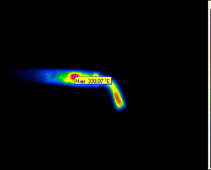
The attached series of thermal images (Figures 8) vividly illustrates the importance of ensuring that the object to be measured is at least three times larger than the unique measuring surface projected at the given distance. Otherwise, for example, if someone were to incorrectly take an "overview" thermal image of a large switchgear or distribution cabinet, the unique measuring spots may contain not only the surface of the object but also its background. Since averaging is done within the measuring spot, the measurement result may be higher or lower than the actual temperature of the object due to the influence of the background temperature. Based on the above, it is already evident that the amount of thermal radiation detected by the thermal camera sensor depends on optical relationships. Therefore, correct focusing deserves special attention, as its failure - contrary to common misconception - leads not only to blurry thermal images but also to serious measurement errors. Optical focusing works in the same way as we are used to in photography: the task of the collector or focus lens inside the camera is to project the incoming rays onto the sensor surface (in traditional photography, onto the film). In case of poor focus, the rays are collected in front of or behind the sensor plane. This results in a blurry image. In the case of thermal imaging, the problem is more significant: only a part of the actual radiation falls on the sensor, while the rest is projected around it. This leads to the measured temperature always being lower than the actual temperature at a high-temperature point (so-called hot-spot). The worse the focus adjustment, the more the measured value deviates from the actual value. With poor focus adjustment, only a part of the radiation falls on the sensor surface (the rest of the radiation hits its surroundings). Therefore: with poor focus adjustment, the thermal camera always shows lower temperatures than the actual surface temperature. This error can reach up to 20-30%!


Note regarding infrared thermometers:It is a common misconception that they measure through laser points or - equally incorrectly - measure the temperature precisely at the point where the laser pointer is visible. This point only marks the center of the measuring surface, or in the case of 2-point or circular laser devices, the edge of the surface, and has nothing to do with temperature measurement. Temperature measurement is done by detecting the thermal radiation emitted from the surface using a sensitive detector and then converting the intensity of the radiation into a temperature value - considering the object's emissivity. For the detection of thermal radiation, neither light nor laser beams are necessary. Eric Rahne, B.Sc. in Electrical Engineering (BME), Vibration Diagnostic Expert, Thermography Expert (Thermograph Level3) pim-kft.hu, termokamera.hu
The content of the publication is protected by copyright, and its (even partial) use, electronic or printed re-publication is only allowed with the indication of the source and author's name, and with the author's prior written permission. Infringement of copyright (Copyright) has legal consequences.
Copyright © PIM Professzionális Ipari Méréstechnika Kft.
2026 | Minden jog fenntartva
Impresszum | Adatkezelés